ISO 3008-4:2021 pdf download – Fire resistance tests — Door and shutter assemblies — Part 4: Linear joint fire seal materials used to seal the gap between a fire door frame and the supporting construction.
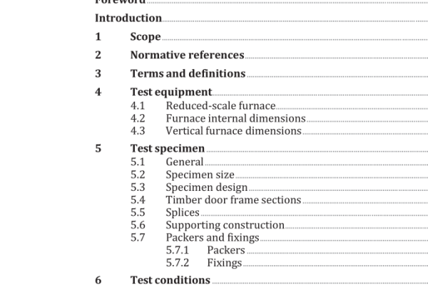
5.2 Specimen size Each test specimen shall be a minimum of 900 mm in length. In instances where the distance between anchors for the fire door frame exceeds 900 mm, the test specimen shall be of a length such that the combined length of linear joint fire seal, door frame and supporting construction is at least equivalent to the maximum distance between door frame anchors. Both a vertical and horizontal specimen of the same linear joint seal design and adjacent fire door frame and supporting construction shall be tested in all cases. The vertical portion represents the fire door frame jamb and the horizontal portion represents the fire door frame header portion. The maximum intended joint fire seal width shall be tested. The minimum intended door frame section width shall be tested. The width of supporting construction shall at least be 300 mm. 5.3 Specimen design Any intended architrave materials shall be fitted over the linear joint seal and become an additional component of the seal. In this case the field of application is limited. 5.4 Timber door frame sections The minimum intended timber density shall be tested. Density and moisture measurements shall be taken prior to testing. 5.5 Splices Where a splice within the seal material(s) and/or backing material(s) is present, in practice, this shall be included within the specimen. This splice shall be located 1/4 of the way down from the top of a vertical specimen and 1/4 of the way from the left-hand edge on a horizontal specimen. 5.6 Supporting construction The supporting construction may be selected from the standard flexible and rigid supporting constructions specified in ISO 834-8 for the required time period. Alternatively, a specific associated construction may be tested, but in this case, the field of application is limited to the specific construction only.
6 Test conditions 6.1 Heating conditions The heating conditions shall conform to ISO 834-1. 6.2 Pressure 6.2.1 For vertical test constructions, the furnace shall be operated such that a minimum pressure of 20 Pa exists at the bottom of any test specimen. 6.2.2 In vertical elements, all splices shall be located within the positive pressure zone so that the pressure at the bottom of the splice is a minimum of 20 Pa for the lowest splice in the test construction. 6.2.3 For horizontal test constructions, the furnace shall be operated such that a minimum pressure of 20 Pa is established at a position (100 ± 10) mm below the lowest point of the test construction. 7 Specimen preparation 7.1 Supporting construction The supporting construction shall be of known fire resistance and representative of that used in practice. 7.2 Joint seal 7.2.1 All materials used in the construction, fabrication and installation of the test specimen shall be representative of the intended application, design, materials and workmanship of those used in practice. 7.2.2 Where voids exist within a joint seal, the ends shall be sealed to prevent air flow through the test specimen.
ISO 3008-4:2021 pdf download – Fire resistance tests — Door and shutter assemblies — Part 4: Linear joint fire seal materials used to seal the gap between a fire door frame and the supporting construction
